Floyds Fork Park Catenary Pedestrian Bridge
Louisville, Kentucky
Client:
Qk4 Architecture Engineering Planning
E. Chestnut Street
Louisville, KY 40204
David J. Reed
Email:
dreed@qk4.com
Date:
Design completed 2013
Scope of work:
Design
Construction cost:
N/A
Services Performed:
- Conceptual design and type selection
- Final design
- Wind section model test and dynamic analysis
Issues:
- Innovative bridge design
- Design for a difficult site
- Historical wind speed analysis and wind section model test
 The Floyds Park Greenway project is located twenty miles east of downtown Louisville in Jefferson County, Kentucky. The Greenway is comprised of a network of trails, roads, pedestrian bridges and parks that are to be constructed adjacent to the Floyds Fork creek on 3,800 acres. Qk4 provided civil and structural engineering design, survey, and construction inspection services to 21st Century Parks (the owner) for those trails, roadways and bridges.
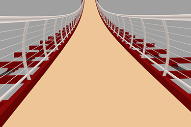
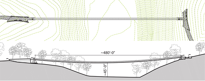
OPAC was engaged by Qk4 to develop the structural type and to prepare design documents for this 480 ft. span catenary bridge. The single span bridge carries a foot path across a valley. It is an unstiffened suspension structure, with cables that support directly the open steel deck framing.
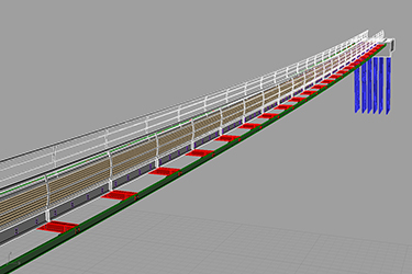
The structural components of the bridge include two pairs of cables, anchored in reinforced concrete abutments, that support floor beams. These beams in turn support the stringers for the foot path. The floor beams are clamped to the cables using bent steel plate cable clamps that are bolted to the bottom flanges of the floor beams. The deck stringers are bolted to the top flanges of the floor beams, with additional diagonal braces to the bottom flanges, to restrain lateral-torsional buckling of the floor beams. The main cables carry all loads to the abutments. The abutments provide a secure anchorage for the bridge cables at the ends of the span. They are reinforced concrete blocks, cast directly against a benched and keyed rock surface. Each abutment is secured to the underlying rock with rock anchors.
Wind engineering were also performed to provide estimates of the stresses, deformations, and aerodynamic stability of the bridge in strong winds. A semi-empirical approach made use of wind tunnel tests of a section model along with computer models of mechanical characteristics.